Faultfinding, and success

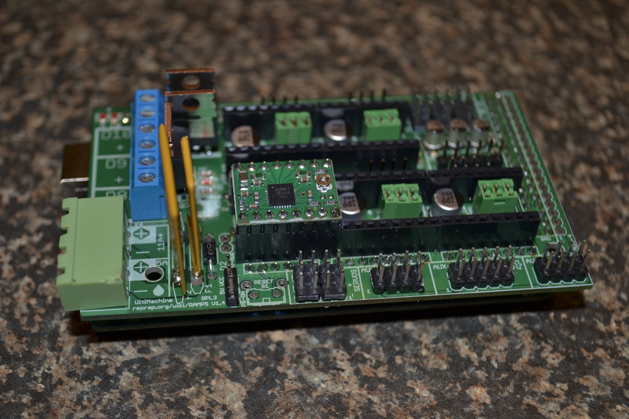
After failing to make the motor run properly, after trying quite a few different firmwares, I came across a testing firmware for RAMPS, that will wiggle all the motors, pulse all the heater outputs, and read the thermistor inputs continually.

http://reprap.org/wiki/File:RAMPS14_test.zip

After fixing the weak connection on the motor connector (usual suspect) I found that all the drivers worked fine, except the X.  All were tested using the same Pololu, so the actual driver can be excused.

This set me on a path that almost cost me the new board… The 10k and 100k resistors were reversed, and in swapping them I unfortunately lifted one of the pads. I had to solder a 10k Resistor on solder-side to fix it up again.  This did not solve the problem though.

With the program running, I measured the frequency of pulses going to each of the pins.  It turns out that all the inputs were fine, except the STEP line.  Well, no STEP, no step.  Makes sense.  I found a dry joint in the header going towards the Arduino, and realized that it was where I tacked the header on to straighten it before soldering.  After a quick re-flow RAMPS is wiggleling on all its axis!

Now I have no excuse but to start assembling the mechanics of the bot.
My RAMPS is dead, Long live RAMPS

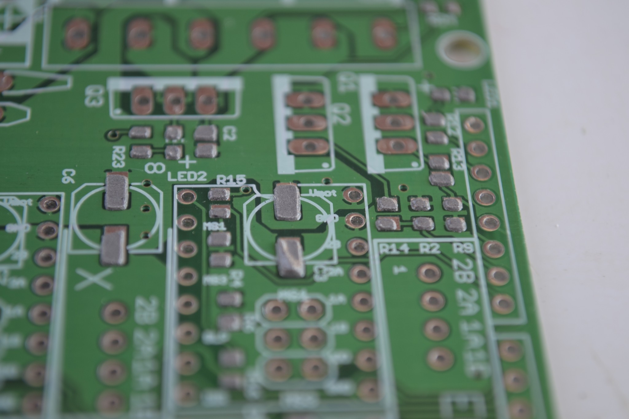
Yes,  even though I tried, my first RAMPS did not survive the fall.  Pads ripped out – Hard to fix on the stepper headers.

Anyhoo, borrowed an hot air solder station from Guy at House 4 Hack Tuesday night and built my next ramps.  It is such a pleasure to work when you have the right tools.  This weekend I will wire it up just to see some steppers turning, to motivate me to continue.

It is so nice to have found some fellow hackers.  Finally people not glazing over when you start to talk about electronics, programming, robotics etc.

Hackerspace

I have been looking for a hackerspace ever since I started tinkering on Morgan, and I finally found one, right on my doorstep!

House 4 Hack is a local Centurion hackerspace, with members participating in Arduino, Reprap, and other Open projects.  They have a couple of bots – perhaps I can get some of the tricky parts for Morgan 0 made this way.

Centurion is turning out to be a very nice place to live it you like to tinker!

Form follows function, or does it?

Something that is very noticeable with all the current reprap and open source 3D prototypers, is that they look very steam-punk.  There are open wires, switches, boards, gears etc. all over the show, with little or no attempts made to conceal the sensitive bits. DIY 3D machines are, for lack of a better analogy, stark naked.  Inside out insects.  Starwars intergalactic fighters with special safe entrances for getting to the power core (to blow it up, and get out unscathed of course)

RepRap, and other “low cost” 3D suppliers can take a lot of pointers from the big players. Make your functional bits in such a way that it protects the sensitive bits.  Sure, it will now make your precious (and complicated) 3D printer look boring, and not anything as complicated as you would like people to think it is.  Just maybe it will now be a little less daunting to use.

We need to make our RepRaps easy to make, easy to use and affordable.  Only then can we even hope that it will take off like it should.

Tragedy struck

On my way to get some more small pieces and plugs for the testing of the board something awful happened.  I left RAMPS on my car roof and drove almost a kilometer before it finally came off with a screech and a slap.  Onto the road.

I only realized what it was a couple minutes later…  I dreaded what I would find.  My precious RAMPS probably run over by a Gautrain Bus.

When I got there it was lying on the line between the two lanes – and still intact save a few bent pins, a broken pololu header and a destroyed 11A resetable fuse.

Repairing the damage now.  It is very fortunate that I decided to leave the Arduino Mega and the Pololu drivers at home!

3D Filament in South Africa

3D printing Filament is one of the largest concerns determining your running costs.  Of course many of the efficient designs are fueled by the extreme cost of filament, but why the extremes?

It seems that there is finally some light in the tunnel.  Somehow the good people at Cad-house managed to bring down filament prices by 50% since I last looked!

http://3d-printer.co.za/3D_Printers/Personal/RepRap_Kits/reprap_kits.html#.UEA74IogdUw

A step in the right direction, although I still believe that we should work together in finding a cheaper solution.  The raw extrusion quality ABS costs only about R6/kg

Ramps done (almost)

It is common knowledge that there are many ways to achive a goal.

Not so well known is that for every successful technique there are just about 50 ways to get it wrong…  There is not one reputable blog or DIY SMT reflow guide that recommends using a heat-gun as a way to reflow your freshly pick and placed SMT PC board.  I tried it early this Saturday.  It was surprisingly successful right up to the point where the Electrolytic capacitors started going off like popcorn, leaving little trails of smoke as it whizzed past my face… Quite entertaining…

After I had my thrills, I went to look for my trusty reflow skillet.  The electric frying pan method always worked for me, and this time – it still did.  Heat guns are for stripping paint, and other DESTRUCTIVE tasks!

I applied the solder paste using a hobby knife blade, and the mask.  Worked well.

I think my solder paste is a bit old. It did not go completely shiny like it once did.  May be a good time to order a new tube.  (Mine has a sell by date of Oct 2007.  Go figure…)

So, in stead of building a couple of RAMPS, I built one, and it still needs to be tested.  At least the LEDs seems to behave in a predictable way – A good sign!

Getting ready to RAMPS

Getting ready to Pick n Place RAMPS

RAMPS sourcing complete.  The last step is to put everything together.  In the picture you see my bare RAMPS board, the pick sheet I made with all the components attached, and the soldermask I hand cut out of 0.15mm thick mylar sheet.

RAMPS 1.4 uses larger SMT components, so hand cutting the solder mask to an acceptable tolerance is not hard.  I have contacted a local laser cutting service to potentially make the mask for the stepstick though.  It is just too fine, especially around the IC.

The previous time I tried to build RAMPS I was way too eager, and used a syringe to apply the solder paste.  The effect was that the components lifted and drifted on the large blobs of solder, causing problems in the denser areas.  I also did not have the right 100uF caps, causing the headers for the pololu / stepstick drivers headers not to fit.

More on Saturday…


Help-Desk
%d bloggers like this: