All good things › Forums › Morgan Builders forum › Morgan Build Morton Grove, IL
Tagged: Z-axis arm assembly question
- This topic has 50 replies, 6 voices, and was last updated 12 years, 11 months ago by
jade39339.
-
AuthorPosts
-
-
July 13, 2013 at 04:56 #584
jade39339
ParticipantHi,
I’m from the states (Morton Grove, IL) and am interested in building the Morgan 3D printer. I would like to use the Morgan design as a stepping stone to later build a laser 3D sintering system such as Andreas has done (http://andreasbastian.com/3dp/3dp.html), but that’s getting the cart before the horse. Currently, I’m sourcing the parts and getting the electronics and steppers at this point. I look forward to digging in and building my printer.
One of my questions which I haven’t seen an answer yet, can I buy selective parts, such as the plastic gearing I see attached to the stepper motors or do I just need to make it by hand?
I won’t need all the parts, which I think I can source, only a selective few that are special. Will you be selling partial kits?
-
July 13, 2013 at 09:36 #586
Quentin Harley
KeymasterI recommend you get someone to print the plastic parts for you. Going the repstrap route is an adventure, but can take a very long time to get every found piece working together.
I can do it for you for $50 plus shipping, but prepare for shipping to cost much more than the parts… South Africa is far far away…
-
July 14, 2013 at 06:10 #594Participant
Hi,
Thanks for the quick response. I’ll see what I can get done for now with my limited funds. I’m thinking about using LEXAN 72 in. x 36 in. sheets and gluing them together to get the thickness of the parts and then machining the parts out of them that way. Sort of like whittling wood, but with band saw, drill press, dremel tool, etc… . Does this sound like a viable options and do you think I would get the desired stiffness in the final part?
Mike B.
-
July 14, 2013 at 07:47 #595Keymaster
It should be fine – at least until you can print yourself a set of parts.
Good luck!
Q -
July 16, 2013 at 22:46 #612
knarfishness
ParticipantHey Mike,
I’m not very far from you, if you need any Morgan parts printed, just let me know.
We also process orders through MakeXYZ, if you’d like to go that route: http://www.makexyz.com/printer/dpr
-
July 17, 2013 at 04:43 #616Participant
Hi,
Thanks for the information. I checked out your site and it looks very nice. I priced some parts on it so I have an idea regarding how much it will cost me. I’ll probably end up having the arms for the Morgan made somewhere and I’ll keep you in mind. Right now I’m trying to get the necessary electronics all rounded up at the moment. I’m working on getting my motors this week. Next week I’ll start on the electronics.
-
July 19, 2013 at 03:26 #634Participant
Ok, so more questions to Quentin,
Not sure if this is already answered, but what should the size/scale of the DXF files be? When I import them into Sketchup, they come out to something like 18-19 ft or in meters something like 5791 mm. What should they be for both the OpenHW_Universal-XPlate and platform_cutting?
Mike
-
July 19, 2013 at 03:48 #635Participant
Also, forgot to ask. What is the thickness of the DXF parts?
-
July 19, 2013 at 04:18 #636
Blaze_1
ParticipantThe DXF files are in mm. I had the same problem initially. If you select options when importing the dxf you can select mm as the scale.(I missed it the first time around, its right to the side of the file select menu after you select import) My measurements in sketchup show 400mm x 460mm for the platform and 220mm x 220mm for the X plate.
Can’t answer to the thickness, probably 1/4″ if you’re going plywood for the platform.
-Remy
-
July 19, 2013 at 04:27 #638Participant
Thanks for the quick response and info, must appreciated!
Mike
-
July 19, 2013 at 20:08 #651Participant
Not a problem Mike, glad to help. I know that issue got under my skin.
Frank, I might be reaching out to you for a set of printed parts as well. I’m in Bloomington, IL so i’m not too far either. Looking forward to seeing how your build comes out.
It’s really exciting to see so many of us in the midwest building Morgans!
-Remy
-
July 19, 2013 at 22:34 #652Participant
How long are the 2 smooth 8mm rods suppose to be?
-
July 20, 2013 at 16:21 #659Keymaster
440mm
-
July 22, 2013 at 17:50 #678Participant
Hi again,
So I’m going the route of the 8mm x 330mm lead screw verses the special setup you’ve done, because of sourcing issue for that part. It’s unclear to me though at the moment how this is being driven mechanically. Can you offer any insight as to how the stepper is attached to the lead screw or is it self apparent once I print the parts? Could you upload a picture of the back and underside of the RepRap Morgan for a fully functioning machine?
I guess I’m having problems visualizing how this is going to work.
Mike B.
-
July 23, 2013 at 18:05 #688Participant
Hi Quentin,
Got some more questions for you.
1. Would I get more accuracy if I use a 0.9 degree motor for the Z axis and would this cause problems?
2. I’m also thinking about making the extruder motor also 0.9 degrees. What are your thoughts on this?
Mike
-
July 24, 2013 at 01:57 #700Keymaster
If you use 0.9 throughout it should not be a problem.
-
July 24, 2013 at 03:00 #702Participant
Thanks for the fast reply.
-
July 24, 2013 at 06:04 #703Participant
I’m having trouble opening the OpenHW_Universal-XPlate.dxf file under the master branch in LibreCAD, is anyone else having the same issue with this file?
-
July 24, 2013 at 06:17 #704Participant
Once again, nevermind. I determined that if I try to selectively pull files from the Github web interface in my Firefox, it saves them in an altered format, and not the original format. I ended up re-downloading a new ZIP file of the entire master build and was able to load all the DXF files just fine after that.
-
July 25, 2013 at 03:17 #711Participant
As god is my witness, I cannot saw a straight line cut if my life depended on it.
Oh well, making the base and top from plywood this weekend.
-
July 25, 2013 at 18:47 #716Keymaster
Have somebody else do the straight cuts for you!
My local builders supply shop has a nice wall mounted radial saw that makes light work of perfectly squared cuts
-
July 26, 2013 at 02:41 #724Participant
Hi Quentin,
Could you contact me and tell me how much you would charge for sourcing the Morgan STL’s parts (8mm) through you?
-
August 2, 2013 at 19:35 #800Participant
How long of GT2 timing belt do I need for both X/Y stepper wheels? I bought a 1100mm belt, will this be long enough for both?
-
August 3, 2013 at 14:48 #806Keymaster
I normally use a meter, so you should have more than enough
-
August 3, 2013 at 15:21 #807Participant
Thanks Quentin!
I’m getting my parts printed this coming week over here (http://uk-3d.com/) in the UK for £ 0.1 cm3. I’ll let you know how they turn out.
Things are starting to come together and I’m chaffing at the bit to start putting stuff together…
Mike
-
August 23, 2013 at 00:31 #1032Participant
Hooray! My parts have shipped! Waiting for them to arrive now!
-
August 23, 2013 at 03:03 #1033
hoff70
ParticipantGood news! I thought you were in the states?
-
August 23, 2013 at 04:23 #1034Participant
I am, I found a guy in the U.K. (David) http://www.uk-3d.com/ that offered to do them for $0.15 cm3. It seemed like a good deal, only thing was I had to wait longer. So now I’m waiting for my parts to arrive to see how they turned out.
-
August 23, 2013 at 04:39 #1035Participant
So how much was the total if you don’t mind me asking? The parts are rather big and I used a lot of filament on mine,
-
August 23, 2013 at 04:44 #1036Participant
About $140 – $160 total, I’m still waiting for the shipping charges to show up. It’s still cheaper than the states, at least that’s what I found so far. I’d wait and see the quality of the parts before you order anything from him. I may be surprised, but at this point I don’t have any reason to believe that I will get bad parts. I’m going to post all the parts online when I receive it.
-
August 23, 2013 at 18:12 #1051Keymaster
How much filament did you use?
Morgan is a bit overweight at the moment – a bit over-engineered. I am whittling down on the parts… Soon you will be able to print new morgans and replacement upgrades that will be a lot lighter on filament.
-
August 24, 2013 at 15:48 #1057Participant
The final total for parts + shipping is around $170 from http://uk-3d.com/.
-
September 15, 2013 at 05:50 #1256Participant
How should the linear bearings sit in the arms? There are 2 raised ridges inside the Z-axis arms. I’ve tried to place both bearing between the ridges, only to find they will not fit. If I place each bearing in the middle of each ridge, they are not aligned correctly for the Z-axis rods. Can you either show me how they should fit in mechanically or explain it to me better?
Sincerely,
Mike Beauford
-
September 15, 2013 at 08:44 #1257Keymaster
The ridges are intended to sit in the rings cut out of the LMxUU bearing bodies. Takes a bit of force to get them in, but afterwards they do not fall down the smooth rods.
I will get a picture for you later today.
Q -
September 17, 2013 at 22:19 #1262Participant
Hi Quentin,
Any update on this?
Mike Beauford
-
September 17, 2013 at 22:27 #1264Participant
I used a vise with a block of wood and a socket about the same size as the bearings to press mine in. They were pretty snug.
-
September 17, 2013 at 23:21 #1266Keymaster
Sorry about the wait… Got sidetracked

-
September 17, 2013 at 23:24 #1267
Ron Hunt
Participant
Little late
-
September 17, 2013 at 23:35 #1270Keymaster
Beat you to it by 3 minutes!
-
September 18, 2013 at 02:13 #1273Participant
I had the same issue. I used the cut off end (downfall) from the rods and worked the bearing into their seats. It took some work to get the bearings both seated and aligned. Using the scrap piece of rod really helped give me leverage without being concerned about damaging the rods themselves
-
September 18, 2013 at 03:48 #1274Participant
Thanks for the tip. I’ll try that when I get back home.
-
October 7, 2013 at 05:45 #1421Participant
Still chugging along with my build. Had other projects that got in the way, but are now starting to wind down.
http://i954.photobucket.com/albums/ae28/jade39339/WP_20131006_006_zpscc3da57c.jpg
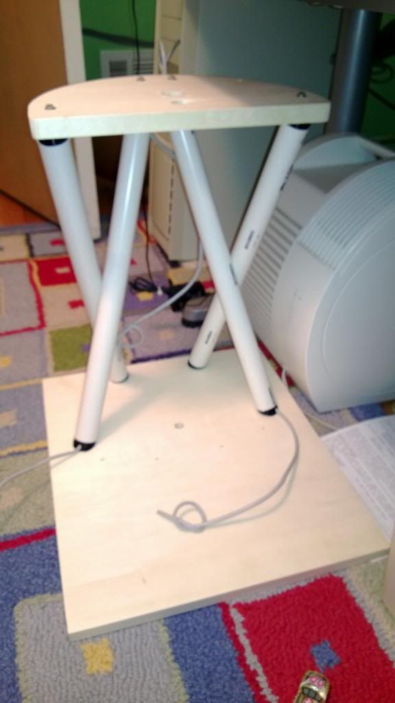
Here’s my latest pic. I noticed when putting my frame together I ran into to issues. 1) the M4 nuts embedded within the PVC come when I was putting the stand together. I ended up drilling a 1/2 hole in order to get the nut out and re-seat it. Tell me there’s got to be a better way to design this so that this doesn’t happen to other people. 2) The PVC pipes are under a lot of stress, is this by design?
Mike Beauford
-
October 7, 2013 at 06:30 #1423Keymaster
Right!
1) I am thinking of using something like this in future:

It will bite into the plastic, and should not just drop put like the normal M4s
2) Yes, the pipes are under stress by design. PVC is very strong and flexible, but not stable enough to keep the platform still by themselves. By stressing the pipes the structure becomes rigid.
-
October 8, 2013 at 16:45 #1436Participant
Hi Quentin,
Got another question for you. Regarding the 4 PVC support pipes. Are they suppose to touch each other on the sides? If you look at the picture up above of my setup, where the pipes cross at the middle part of the X is where they touch, is this by design or should they not touch?
Mike
-
October 9, 2013 at 07:35 #1437Keymaster
By design the pipes try to occupy the same space, making them flex around each other.
PVC is cheap, tough as nails and available worldwide. The only problem with using PVC as a structural element is that it is too flexible, making for floppy structures. If you stress them, the structure firms up because the PVC does not want to flex more without a fight.
It is reasonably tough to get the screw of the last pipe to get connected at the top. I normally grab it with my hand, including the smooth rod in the grasp. This allows me to put it until the hole lines up for the placement of the last screw.
-
October 10, 2013 at 05:32 #1465Keymaster
-
October 10, 2013 at 06:13 #1466Participant
That happened to me after the first time I took the frame apart. Super glued it and it’s solid as a rock, just as Q said.
-
October 10, 2013 at 07:09 #1467Participant
Thanks Quentin for the info, I’ll give it a shot and let you know how it goes.
-
September 5, 2013 at 07:05 #1155Participant
Just got my printed parts, now I’m aiming to start assembling it after next week.
-
September 18, 2013 at 00:41 #1271Participant
Thanks guys. So the issue I’m seeing is when I do line them up on the ridges inside, 1 or both of the bearings seem to be mis-aligned on the rod. They do not slide smoothly at all, and sliding the rod up and down on the shaft produces a scraping sound. Should the linear bearings just self align or do I have a set of brand new bearings that are bad?
Any ideas?
-
October 10, 2013 at 04:03 #1462Participant
Hi Quentin,
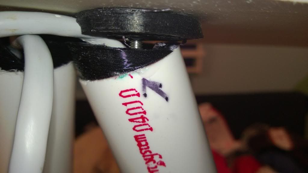
Found out why my platform was rocking and seemed to be a little loose. It looks like one of my ported ends on the rear PVC pipe snapped off its base.
http://i954.photobucket.com/albums/ae28/jade39339/WP_20131009_005_zpsaf7f0412.jpg
Do you think I can re-glue it with super glue to get it to hold and re-attach?
-
-
AuthorPosts
- You must be logged in to reply to this topic.