New RAMPS built

Last night I completed my second (third…) RAMPS board. It is becoming very easy now, especially since I expanded my SMD toolkit.

20130212-090907.jpg

The most important additions are possibly the solder paste gun, fresh solder paste, and the liquid flux pen. The solder paste gun works like a caulking gun, except that the trigger is hair fine, with a long lever, allowing you to squeeze the tiniest drops of paste onto the pads. Works a treat!

See my new RAMPS below.

20130212-091239.jpg

It is populated fully in SMD components, but through-hole stuff was added minimally. I can still add stuff later if required. I tested it, working perfectly so far.

I also had time to do the micro-current hack on my pololu drivers, replacing R4 with a zero-ohm resistor.

20130212-091603.jpg

Now everything is in place for the big push in the firmware.

Next:

    Install RAMPS with at least the basic motor functions
    Complete and test inverse kinematics
    Install limit switches on the theta and phi axis, and write an auto homing routine

Good times!

Marlin kinematics update

Stuck in a city far away from my lab, I had to resort to playing with the firmware.

Based on Johann Rocholl’s Marlin for Rosstock  (a delta bot), this is the initial kinematics change I would like to test when the bot itself is finished:

in Marlin_main.cpp:

void calculate_delta(float cartesian[3])
{

 // SCARA "X" = theta
 // SCARA "Y" = psi+theta, motor movement inverted.
 //static float SCARA_C2, SCARA_S2, SCARA_theta, SCARA_psi - Defined above...
// Length of inner support arm
 //#define Linkage_1 150 //mm
// Length of outer support arm
 //#define Linkage_2 150 //mm
// SCARA tower offset (position of Tower relative to bed position)
 //#define SCARA_offset_x 100 //mm 
 //#define SCARA_offset_y -60 //mm
 SCARA_C2 = (sq(cartesian[X_AXIS])+sq(cartesian[Y_AXIS])-Linkage_1_sq-Linkage_2_sq)/(2*Linkage_1*Linkage_2);
 SCARA_S2 = sqrt(1-sq(SCARA_C2));

 SCARA_K1 = Linkage_1+Linkage_2*SCARA_C2;
 SCARA_K2 = Linkage_2*SCARA_S2;

 SCARA_theta = atan2(cartesian[X_AXIS],cartesian[Y_AXIS])-atan2(SCARA_K1, SCARA_K2);
 SCARA_psi = atan2(SCARA_C2,SCARA_S2);


 delta[X_AXIS] = SCARA_theta * SCARA_RAD2DEG; // Multiply by 180/Pi - theta is support arm angle
 delta[Y_AXIS] = (SCARA_theta + SCARA_psi) * SCARA_RAD2DEG; // - equal to sub arm angle (inverted motor)

 delta[Z_AXIS] = cartesian[Z_AXIS]; // Standard Z for Morgan
}

Now the wait…

Inverse Kinematics

The web is full of wonderful sources of information, and you can easily find all the math required to drive a SCARA arm using inverse kinematics online. Turning it into efficient code… not so easy to find. This is the part of the design that actually scared me the most.

I decided to dig into it a bit tonight, and I have to say that after grabbing a pencil, drawing some pictures and writing out some of the equations it has become a lot clearer, and I even have hope of running the kinematics straight from the Arduino Mega.  Who knew that the maths I had to struggle through at Varsity would actually come in handy after all!

When the firmware is running, I will publish my Marlin fork to github.  I aim to integrate it in such a way that it could possibly be pushed into the main branch of marlin without breaking anything else, but that is definitely a long time goal.  Let’s get Morgan running first!

Progress

This weekend I made quite a bit of progress.

20130203-163637.jpg

In these images you can see the updated motor holders, the new bed bracket with lead screw, and the power supply roughly in the right spot, ready for the electronics.

What you cannot see, is the new inner shaft of the SCARA drive, that now consists of the threaded rod and a 15mm copper pipe. It turns out that the elasticity of the rod itself is now the weak link in the design… The double shaft successfully dampens and oscillations that were apparent before.

20130203-163917.jpg 20130203-163900.jpg

Next:
Bed leveling, and hotbed. Building of RAMPS for morgan ( my current RAMPS is doing Ecksbot duty ), and the upgrade and mounting of the extruder.

Watch this space!

Frame update

Finally time for some work!

The frame, as it was up until now has some slight but problematic structural deficiencies, and it is time for a redesign.

frame_mk2frame_mk2_2

The new frame still use PVC pipe, but used in a triangular configuration that should get rid of most of the unwanted movement.

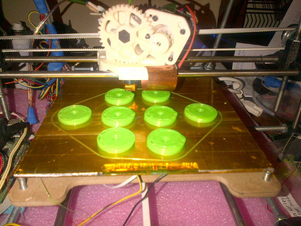
In the photo below, you can see the pipe adapters during the print.  My first attempt last night was the victim of a filament spool tangle, and only printed half way…


2013

Well, a new year has come, the Mayans were wrong (what did you expect) and I am back at work.

2012 brought us “The Plan”, the Electronics, the firmware, the loaner, and the frame.

2013 is the birthyear of Morgan.  There are a couple of challenges remaining, not least of which would be the custom firmware for the Morgan’s SCARA configuration.

I hate to be a tease, but things are really starting to shape up.  Source files will be made available one week after the first successful print (regardless of quality).

More soon

Help-Desk
%d bloggers like this: